Q-see QT528 User Manual
Browse online or download User Manual for Car DVR Q-see QT528. Q-See QT528 User Manual
- Page / 98
- Table of contents
- BOOKMARKS
- USER MANUAL 1
- CAUTION 2
- Table of Contents 3
- 1. INTRODUCTION 5
- 2. GETTING STARTED 7
- 2.4 Rear Panel Layout 10
- 2.5 Remote Control 10
- 3. BASIC FUNCTION 13
- 4. MAIN MENU SETUP GUIDE 16
- Fig 4-22 Sensor-Schedule 29
- Fig 4-24 Motion-Area 30
- Fig 4-28 Other Alarm 32
- 4.6.3 Email 35
- Fig 4-36 Add User-Authority 38
- Fig 4-40 Preset Set-Setting 41
- Fig 4-41 Cruise Set 41
- 4.9 Advanced 42
- 4.91 Reset 43
- 4.9.2 Import/Export 43
- Fig 5-5 Backup Information 46
- 6. DVR MANAGEMENT 47
- Fig 6-6 Manual Alarm 49
- Fig 6-7 Disk Manager 49
- 7. REMOTE SURVEILLANCE 50
- 51
- Fig 7-5 Static IP 52
- Fig 7-6 PPPoE 53
- Fig 7-7 DDNS 54
- Fig 7-8 Registration 55
- Fig 7-9 Domain Name 55
- Fig 7-13 myq-see 57
- Fig 7-25 Right Key Sub Menu 68
- as required 69
- Fig 7-32 Remote Menu Setup 72
- 8. MOBILE SURVEILLANCE 73
- 8.2 Phones with Symbian 75
- Information view 85
- Requires Blackberry OS 5 86
- 9. PRODUCT SPECIFICATIONS 90
- Appendix A FAQ 91
- PC MODULE PARAMATERS 92
- Q-See Product Warranty 96
- Customer Information Card 98
Summary of Contents
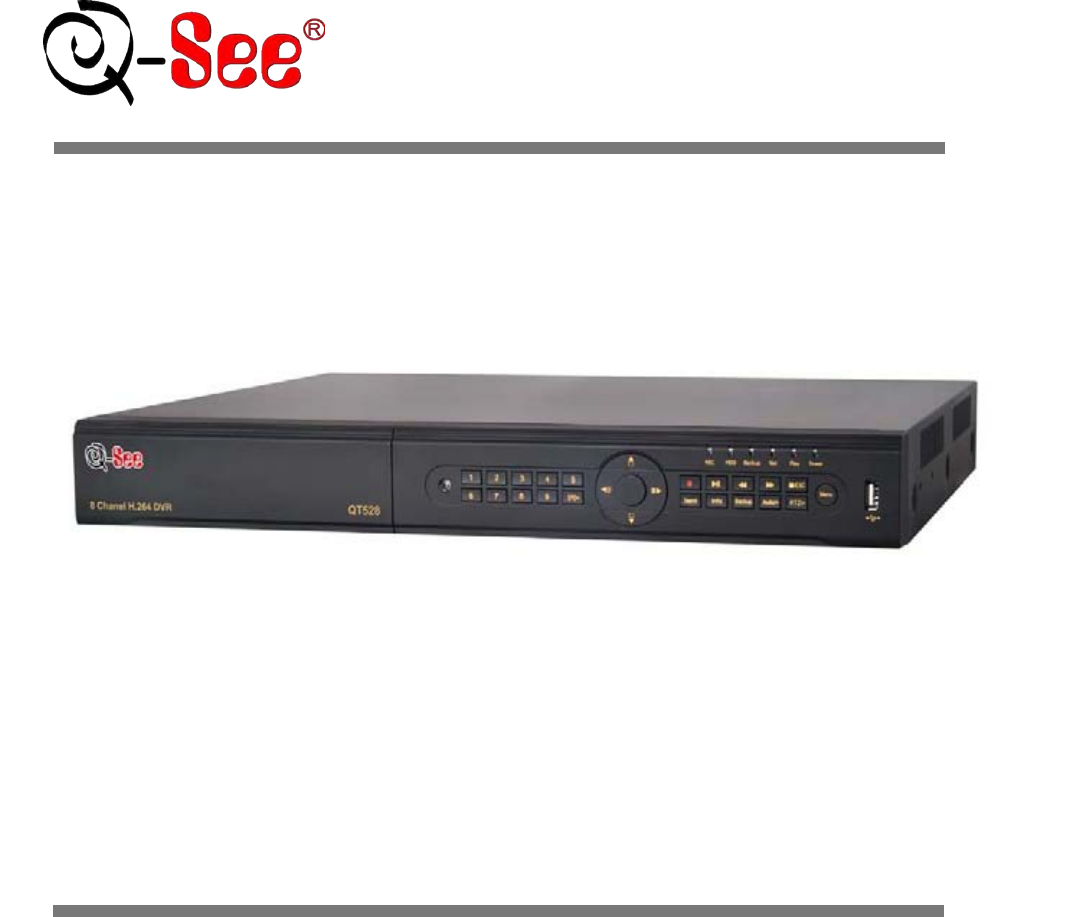
H.264 Dual Stream Network DVR 8 Channel CIF@240fps & D1@240fps Digital Video Recorder USER MANUAL Model #: QT528 www.q-see.com R
9 2.4 Rear Panel Layout Fig 2.5 Rear Panel Item Name Description 1 PTZ Connect to speed dome. Y means “+”, Z means “-” 2 K/B Connect to PTZ k
10 Fig 2.6 Remote Control Item Name Function 1 Power Button Stops firmware so that you can power down DVR 2 INFO Button Get information about th
11 2.6.2 Use Mouse In Live: Double-click left button on one camera to be full screen display. Double-click again to return to the previous screen
12 3. BASIC FUNCTION 3.1 Power On/Off Before you power on the unit, please make sure all the connections are good. 3.1.1 Power On Step 1: Conne
13 3.2 Login User can login and logout of the DVR system. User cannot do any other operations except changing the multi-screen display once logout.
14 3.3.1 Live Playback Click the Playbutton to playback the record. Refer to Figure3-3. User can operate by clicking the buttons on the screen. F
15 4. MAIN MENU SETUP GUIDE Click right mouse or press ESC button on the front panel, the control bar will display on the bottom of the screen,
16 4.1 Basic Configuration Basic configuration includes three sub menus: system, date& time and DST. 4.1.1 Setup Step1: Enter into Setup conf
17 4.1.2 Time & Date Step 1: Enter into system configurationbasic configurationtime & date; refer to Fig 4-4: Fig 4-4 Basic Configuratio
18 4.2 Live Configuration Live configuration includes four submenus: live, host monitor, SPOT and mask. 4.2.1 Live In this interface, user can
1 CAUTION Please read this user manual carefully to ensure that you can use the device correctly and safely The contents of this manual are sub
19 4.2.2 Host Monitor Step 1: Enter into system configurationlive configurationhost monitor; refer to Fig 4-8: Fig 4-8 Live Configuration-Host
20 4.2.4 Mask User can setup private mask area on the live image picture, maximum of three areas. Fig 4-10 Live Configuration-Mask Setup Mask
21 4.3 Record Configuration Record configuration includes five sub menus: enable, record bit rate, time, recycle record and stamp. 4.3.1 Enable
22 4.3.2 Record stream Step 1: Enter into system configurationrecord configurationrecord bit rate; refer to Fig 4-12: Fig 4-12 Record Configura
23 4.3.3 Time Step 1: Enter into system configurationrecord configuration time; refer to Fig 4-13: Fig 4-13 Record Configuration-Time Pre-al
24 4.3.5 Stamp Stamp:User can display the channel name and time stamp on video. Step 1: Enter into system configuration record configuration sta
25 Schedule configuration includes three sub menus: schedule, motion and alarm. 4.4.1 Schedule Step 1: Enter into system configurationschedule co
26 Fig 4-17 Schedule Configuration-Motion Step 2: The setup steps of motion are similar to schedule; user can refer to 4.4.1 Schedule for details
27 4.5.1 Sensor (to setup optional external motion sensors) Sensor includes three sub menus: basic, alarm handling and schedule. ① Basic Step 1:
28 Fig 4-21 Alarm Handling-Trigger Step 3: Checkmark Buzzer, there will be triggered buzzer alarm out; Full screen alarm: when triggered alarm,
2 Table of Contents 1. INTRODUCTION ...
29 ① Motion Step 1: Enter into system configurationalarm configurationmotion; refer to Fig 4-23: Fig 4-23 Alarm Configuration-Motion Step 2:
30 user can adjust its value according to the practical conditions; click icon, set the whole area as detection area; click icon, the set detec
31 Step 1: Enter into system configurationalarm configurationvideo loss; refer to Fig 4-27: Fig 4-27 Alarm Configuration-Video Loss Step 2: The
32 Alarm out includes three sub menus: alarm out, schedule and buzzer ① Alarm out Step 1: Enter into system configurationalarm out; refer to F
33 4.6.1 Network Step 1: Enter into system configurationnetwork configurationnetwork; refer to Fig 4-29: Fig 4-29 Network Configuration-Netwo
34 User name User name of broad band account Password Password of broad band account DDNS server DDNS server Website provided by dynamic domain na
35 Fig 4-30 network configuration-email SMTP Server/Port: the name and port number of SMTP server. Tick off “This server requires a secure connecti
36 DDNS server DDNS server Website provided by dynamic domain name supplier. The options: myq-see.com and www.dyndns.com User name User name for l
37 ② Authority: Step 1: Enter into Add userauthority; refer to Fig 4-36: Fig 4-36 Add User-Authority Step 2: In the authority interface, assig
38 Fig 4-37 P.T.Z Configuration-Serial Port Step 2: Checkmark Enable, setup the value of address, baud rate and protocol according to the settings
3 4.9 Advanced ...
39 Fig 4-38 P.T.Z Configuration-Advance Step 2: In the Advance interface, click preset “Setting” button, a dialog box will pop-up shown as Fig 4-3
40 Fig 4-40 Preset Set-Setting b. User can control the dome rotating up, up left, down, right down, left , left down, right and up right and stop
41 Fig 4-42 Cruise Set-Modify Cruise Line a. Click Add icon to set the speed and time of preset point; select a preset point, click Delete ico
42 4.91 Reset Note: Before you do the reset, we recommend you do an Import/Export first to save all of your settings (see instructions below). Af
43 5. RECORD, SEARCH, PLAYBACK AND BACKUP Search configuration includes three submenus: time search, event search and file manager. 5.1 Time Searc
44 5.2 Event Search Step 1: Enter into Search configurationevent search; refer to Fig 5-2: Fig 5-2 Search Configuration-Event Search Step 2: Cl
45 (unless you format the hard drive). ② Unlock: check a locked file, click Lock button to unlock this file ③ Delete: check an unlocked file, clic
46 6. DVR MANAGEMENT 6.1 Checking System Information Check system information includes five submenus: system, event, log, network and online use
47 6.1.1 Log Information In this interface, user can check relevant log information according to selected date; refer to Fig 6-3: Fig 6-3 Log In
48 6.1.2 Manual Alarm In this interface, user can check the relevant parameters of manual alarm; refer to Fig 6-6: Fig 6-6 Manual Alarm 6.1.3 D
4 1. INTRODUCTION 1.1 DVR Introduction This DVR uses high performance video processing chips and an embedded Linux system. It utilizes many advan
49 7. REMOTE SURVEILLANCE 7.1 Network Access Accessing the DVR from a computer attached to the same router: If you are only going to access the
50 Fig 7-3 DHCP Static IP: You will need to setup the network settings on the DVR to match the
51 Fig 7-5 Static IP For the DVRs IP address you would enter the same first 3 sets of numbers as the gateway and select a fourth set of numbers th
52 Fig 7-6 PPPoE DDNS: You can access the DVR through a static or dynamic IP address; however a dynamic address can change from time to time. How
53 Fig 7-7 DDNS Setting up MYQ-SEE DDNS: NOTE: Before you setup DDNS you must first set up Port Forwarding as directed in Section 7.3 PORT FO
54 Fig 7-8 Registration a. The next screen will ask you to create a domain name. Domain names must start with an (a-z) or (0-9) and cannot con
55 a. Once you have completed steps a-d, go to the Main Menu and select the Setup icon (Red box in Fig 7-10), then select the Network icon (Red b
56 d. After you enter the information click on the Test button (Green box in Fig 7-13) and wait until you see the OK message in the bottom left han
57 b. Choose your DVR or Series (QT, QSDT, QR, QS etc) from the list provided c. Select the make and model of your router from the list
58 e. Follow the instruction on the website (The top set of instructions are done on the DVR. The bottom set of instructions are done on the rout
5 ALARM 1 channel alarm output and 8 channel alarm input available Supports scheduling for motion detection and sensor alarm Supports pre-reco
59 c. Verify that the port(s) is open. i. If the port is open, you will see the following message:”Success. I can see your service…” ii. Go
60 i. After your ISP unblocks those ports for you, repeat steps i and ii. When you access the DVR from a remote computer you also need to use a
61 Pic 9 Pic 10 Click on Security Tab. Click on Trusted Sites. Click on Sites button. Pic 11 Unc
62 5 If you get a error message that says the program cannot load because the publisher is unknown or the program is unsigned, go to internet exp
63 connect to same Router as your DVR). Notice: If you cannot use HTTP port 80 or 6036 because the port is being used by another program, or it is b
64 7.5 Using the Remote Access Software Once you have setup Internet Explorer you can access the DVR through a browser window. If you are accessing
65 Note: click button to record manually and the recorded file will be saved on your PC hard drive. Screen display mode: Click the icon beside
66 Color Adjustment: Drag the slide bar to adjust Brightness, Contrast, Hue, and Saturation. Click Default to reset them to original value. BUTT
67 Right click the mouse on the live interface to generate a pull-down menu as shown below: Fig 7-25 Right Key Sub Menu Stream: this DVR suppor
68 Fig 7-27 Time Search Interface Step 2: Click “Search” button. The record data will be displayed in the data information list box. The highligh
6 2. GETTING STARTED Check the unit and the accessories immediately after opening your system. Please disconnect the power before connecting to
69 By Event Search: Step 1: Enter into Searchevent search; refer to Fig 7-29: Fig 7-29 Event Search Interface Step 2: Click the highlight date
70 7.6.2 Remote Backup Click Backup button to enter into backup interface, refer to Fig 7-31: Fig 7-31 Remote Backup Interface Step 1: Select ch
71 Fig 7-32 Remote Menu Setup The sub menu lists and the options in every item are similar to those on the DVR. Please refer to Chapter 3 Main Men
72 8. MOBILE SURVEILLANCE This DVR supports mobile surveillance by Iphone, or smart phones with Windows Mobile Pro and symbian OS on 3G networks. W
73 Step 5:Input the DVR’s address, ID and password respectively in the columns of “Server”, “User” and “Password”, and click “Go” to log on the DVR.
74 8.2 Phones with Symbian Please use the smart phones with Symbian versions supported by this unit. Step 1:First enable the network access on the
75 Step 7:Click System setting--->Login Setting to enter login interface. Step 8:Input the DVR’s address, ID and password respectively. Then sa
76 8.3 For iPhone Mobile Clients 1. Installing through iphone. Step 1. Open App Store function of iphone Step 2. Enable “search” function to s
77 Step 1: Install iTunes store in PC and then login Step 2: Connect iPhone and PC Step 3: Enable “search” function to search “Super
78 2. Main Interface 【Playback】 playback record file 【Image】 image view 【Log】 log record 【Server List】 device list 【Live】 live view 【Settings】 sof
7 2.2 Installing Hard Drive Notice: 1. This DVR supports two SATA hard drivers or one SATA hard drive plus one DVD-RW Writer. 2. Ple
79 Switch to the single image Switch to four images Upward rotates the PTZ Downward rotates the PTZ Leftward rotates the PTZ Rightward rotates
80 Main parameters for mobile phone video config Record file clip size: Single video size. When the video size is greater than setup value, change
81 8.4 For Android Mobile Clients Software Installation Step 1: run Google Market program Step 2: search”SuperCam”
82 Main menu 【Playback】 playback record file 【Image】 image view 【Live】 live view 【Log】 log record 【Server List】 device list 【Settings】 software se
83 Image view Record playback (Fig 3) (Fig 4) Click the record file (Fig 3) to playback (Fig
84 Config interface Alarm setting Tick off Sound Alarm ,when Video Loss/Sensor/Motion happen,trigger sound alarm; Tick off Vibrate Alarm, when Vi
85 8.5 For Blackberry Mobile Clients Requires Blackberry OS 5 Installation instruction for BlackBerry Mobile phone Client 1. Open the browser on B
86 2) Enter into Menu->Option->Cache Operations, clear up browser cache. Note:When you use the SuperCam software in mobile phones with tou
87 3. Live view Mark 1 Current viewing channel Mark 2 Channel status Switch channels PTZ, click to switch to Fig 2 interface Snap
88 Software configuration Information view
8 2.3 Front Panel Descriptions Fig 2.5 Front Panel Item Name Description 1 Power Status Power indicator, when connection , the light is blue
89 9. PRODUCT SPECIFICATIONS ITEM DEVICE PARAMETER SPECIFICATION COMPRESSION COMPRESSION FORMAT Standard H.264 Baseline VIDEO VIDEO IN COMP
90 Appendix A FAQ Q1. The DVR does not start after connecting the power, what is wrong? a. The power adapter may have been damaged, or is not pr
91 Q10: How do I input password and digital numbers? To input password and digital numbers click the box behind password or items where you need t
92 Q16:.What are the PC configurations for 8-ch real time access with fully open mainstream channel? PC MODULE PARAMATERS CPU Intel Core(TM)2 Du
93 Appendix B Calculate Recording Capacity (D1) Users can calculate the size of hard disk according to the saving time and DVR recording settings.
94 APPENDIX B: CALCULATE RECORDING CAPACITY (CIF) Users can calculate the hard drive size needed according to the time saving specification and DVR
95 Appendix C Compatible Devices 1. Compatible USB drive after test. Brand Capacity SSK 512MB, 1G, 2GB Netac 4GB Kingston 2GB Aigo 2GB Smatter vid
96 (4) Equipment damage caused by the maintenance of personnel not authorized by Q-See. (5) Product sold over 12 months ago. In order to fulfill th
Customer Information Card User’s Name Mr./Mrs. Company Name Postal Address Postal code Phone Number E-mail Model Number of Product Serial Numb
Related products and manuals for Car DVR Q-see QT528
 (27 pages)
(121 pages)
(85 pages)
(49 pages)
(35 pages)
(31 pages)
(101 pages)
(36 pages)
(121 pages)
(47 pages)
(100 pages)
(27 pages)
(121 pages)
(85 pages)
(49 pages)
(35 pages)
(31 pages)
(101 pages)
(36 pages)
(121 pages)
(47 pages)
(100 pages)
© 2020, manymanuals.com. All rights reserved. | 1.850 s |
 Manymanuals.com
 Manymanuals.de
 Manymanuals.fr
 Manymanuals.it
 Manymanuals.pl
 Manymanuals.cz
 Manymanuals.es
 Manymanuals-pt.com
Comments to this Manuals